
|
OpusFSI Flight
Simulator Interface for |
|

OpusFSI_v5_Overview OpusFSI_v5_User_Guide OpusFSI_v5_Getting_Started_Single_PC OpusFSI_v5_Getting_Started_Networked_PCs OpusFSI_v5_Live_Weather OpusFSI_v5_Live_Camera OpusFSI_v5_ButtKicker
The OpusFSI Live Camera Interface
Adjusting the Camera Automatic Head
Movement (AHM)
When
AHM is enabled (accessed via the AHM
button in the DHM dialog) the view will automatically change to look into the turn. You can
configure the view to change either in increments or in a continuous smooth
movement.
N.B.
Automatic Head Movement is
automatically disabled when you are using TrackIR.
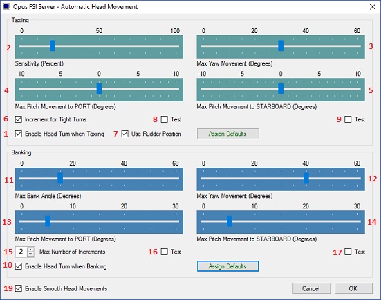
1. Enable
Head Turn when Taxiing
Enable
to set AHM Taxiing effects.
2 - 5. Taxiing Sliders
For
AHM when taxiing you can alter the sensitivity for the calculated turn radius.
You can alter the sensitivity (2) in percent, maximum yaw movement (3) in degrees, maximum pitch movement to the left (port) in degrees
(4), and
maximum pitch movement to right (starboard) in degrees (5).
Adjust
these sliders to set your desired parameters for the initial automated head
movement. All incremented movements are calculated from this base level by
increasing the specified angles and sensitivity. If in doubt then click on the
Assign Defaults button to set the recommended defaults.
6.
Increment for Tight Turns
Enable
to set another level of increment for the AHM Taxiing effects.
7. Use
Rudder Position
Uses
the current rudder deflection for the AHM Taxiing effects as opposed to the
simulator's 'delta heading' variable. The heading variable can be a little
erratic and so requires both hysteresis and a small reset delay. If the Use
Rudder Position option is selected the AHM taxiing effects are disabled
whenever the aircraft's ground speed and throttle position are greater than or
equal to 30kts or 75 percent respectively.
You
can tick one of the Test checkboxes to get some idea of the effects of the AHM
whilst taxiing to the left (port) and right (starboard).
Assign Defaults
The
Assign Defaults button can be used to reset all sliders back to their default
settings.
10. Enable
Head Turn when Banking
Enable
to set AHM Banking effects.
11 - 14. Banking
Sliders
You
can alter the AHM maximum bank angle (11), the amount of head rotation in yaw (12) and pitch for turns to the left (port 13) and right (starboard 14). Adjust these sliders to set your desired parameters for the
initial automated head movement. All incremented movements are calculated from
this base level by increasing the specified angles and sensitivity. If in doubt
then click on the Assign Defaults button to set the recommended defaults.
15. Max
Number of Increments
Set
the maximum number of increments for the AHM Banking effects. The maximum number
of increments can range from 1 to 4, the recommended setting is 2.
16 - 17. Test
Checkboxes
You
can tick one of the Test checkboxes to get some idea of the effects of the AHM
whilst banking to the left (port) and right (starboard).
Assign Defaults
The
Assign Defaults button can be used to reset all sliders back to their default
settings.
19. Enable
Smooth Head Movements
Tick
the checkbox to select smooth head movements as opposed to stepped 'snap to'
increments. Note, the smooth movement option is intended for the higher
performance systems. All head movements are performed in such a way as to have
minimal impact on your simulator's frame rates. if you experience any FSX/P3D
DOF Errors reported in the main Spy window, or your head movement appears very
jerky then you should immediately disable the smooth movement option and use the
default 'snap to' movements.
User Note
The
AHM effects are enabled the first time the camera view is displayed. If the
camera view has been assigned to a keyboard key or joystick button then you can
use that same input to toggle the AHM effects on and off. When toggled off, the
AHM effects will automatically toggle back on as soon you recover from the turn
whilst taxiing or level the wings after a banked turn.
Reselect the camera view to toggle any
active AHM effects on and off.
Sim
Add-on Menu and Shortcut Controls
Assigning
Joystick Buttons and Keyboard Keystrokes
All
button and registered key events are displayed within the Spy window when the
button or key is pressed. Keyboard events do not appear in Spy whilst editing cameras, only after
they have been saved and edit mode is exited. If they are not displayed then the
button or key is invalid, either not enabled or registered within FSX, already assigned elsewhere (i.e. FSX, 3rd party add-on etc), or just an illegal entry.
The
same joystick button or keyboard input can be assigned to multiple camera views.
In such cases, repeated use of the assigned button or key will cycle through the
assigned camera views. The
cycle will apply to the aircraft associated with the camera view, which may be a
single aircraft, a group, or all aircraft according to what you have configured.
Alternatively you can
assign a button and/or key to the same view type for each aircraft
type/group, e.g. the Captain's view is the same key/button for all
aircraft. We normally assign the
same key combos to external views so we can just cycle through them.
Joysticks
The
OpusFSI software will accommodate up to eight joysticks or game controllers connected to the FSI SERVER
system, with up to 32 buttons on each, and up to 32 keyboard assignments.
The Hat Switch and Panning
The
Hat switch is not a button and cannot be assigned in the usual manner since FSX
uses it for panning. The Hat switch can be used to pan the view when the TrackIR
device is paused (F9). If you have disabled your controllers in FSX and are
using FSUIPC then you can enable mouse wheel button panning and that also
re-enables the hat switch on the joystick. Alternatively you can use FSUIPC to
convert the hat switch data to keystrokes. ctrl+shift+0 through to ctrl+shift+8
are unassigned in FSX and you can use some of those as the keystrokes to trigger
Live Camera views.
Keyboard
Each
keyboard assignment may consist of a combination of up to two modifier keys
(Alt, Ctrl, or Shift) with a normal keyboard key. The entry is not case
sensitive. The numeric pad keys 0 to 9 can be used but they must be assigned
with the Num Lock ON (for recognition), and used with the Num Lock OFF within
FSX/P3D. This is a quirk of the simulator and not the OpusFSI software.
N.B. The Insert, Delete, Home, End, Page Up, Page
Down, Left, Right, Up, and Down keys cannot be assigned to camera views.
If you assign numeric keys and have the Local
Weather Report window displayed then FSX will interpret the numeric keys for the
weather report window which in effect means you have to press the key twice, the
first time the weather report window will close and the second time the camera
view will change.
Shortcut Controls
You can assign shortcut control keys to cycle
the camera views forward (next) and cycle the camera views backward
(last) between views matching the currently selected view mode (virtual
cockpit, 2D cockpit, or External Aircraft camera views for the currently
selected aircraft). There is a difference between the actions of the
Shortcut View Cycling commands and the way 'common' camera key or
buttons are processed when configured into the actual Live Camera views.
The Shortcut key/button will only cycle the views
with the same view mode that was last selected onto the display through
the Live Camera interface. So the Shortcuts will cycle through all your
VC views or all your External views depending on what was last selected
through Live Camera actions.
The common key (or
button) is assigned to groups of views, assigned within the camera views
themselves. I use a common X key configured in all my camera views. This
common key (or button) will cycle through all assigned camera views
irrespective of the camera view mode.
Shortcut Commands - Cycle
through relevant views with the same view mode as the current
view.
Camera Commands - Cycle
through all cameras assigned with the same common key/button.
Refer
to the description of Shortcut
Controls in the OpusFSI_v5 User Guide.
Creating
Panel (Flight Control) Windows
Firstly,
panel windows, or any window used to control the aircraft's flight, must be
displayed on the main 'flying' server system. All client systems are used purely
as view controllers, offloading much of the display workload from the main
'flying' server.
If
you wish to create a separate panel view on your server then follow the above
instructions to create a new Windowed View and associate it with your aircraft.
Select the required Virtual or 2D camera type depending on the cockpit you are
using, then adjust the camera's coordinates and zoom settings to create a close
up view of the instrument panel or panels. You may find it helpful to undock the
main simulator's view during this process, this will allow you to adjust the
shape of the window to match the panel(s) and your intended screen layout. You
may also find it helpful to use the Stepped camera control to make fine
adjustments to the camera's eye position.
When
finished, make sure you save your new camera configuration using the Save
Cameras button and re-dock your simulator's main view.
2D
Panel
It
is not possible to determine in software whether you have the 2D panel enabled
or disabled within the simulator. This problem mostly affects the OpusFSI server
system since all client systems normally have the 2D panel transparency set to
100%. If you have set up a scenic view intended to be displayed with the 2D
panel disabled and display the view with the 2D panel enabled, the eye position
will not be as expected. In such cases use the Shift-1 key sequence to toggle
the 2D panel OFF.
On the main 'flying' OpusFSI server
system, toggle the 2D panel on and off display using the Shift-1 key sequence.
Normally it will be off for all scenic views and only enabled if you
specifically want to fly with the 2D panel.
Warning,
do NOT set the 2D panel transparency on your main OpusFSI server to 100% as this
may result in making the aircraft's docked panels invisible.
Incorrect
Eye Position for 2D 'Scenic' Views
Refer
to the above 2D Panel section. For
scenic views the eye position will be incorrect if you have the 2D panel
enabled. Use the Shift-1 key sequence to toggle the 2D panel OFF on your server
system's display.
Creating a Virtual Cockpit Camera View
A
few words before you begin ...
You
will be needing to open and access the Camera dialog within your main OpusFSI
server program, or simply your OpusFSI program if you don't have a networked
system. In each case, I am referring to the FSI SERVER program installed in your
c:\OpusFSI_v5 folder. It is therefore essential to set the simulator into windowed
as opposed to full screen mode so that you can see and access the server
program's form.
Select your aircraft in the sim before you start
You
will be creating a camera view for a specific aircraft's virtual cockpit so it
is best to load that aircraft into the simulator before you get started. The
OpusFSI camera editing software will not do this for you.
Selecting the computer system
If
you just have a standalone PC you can ignore this step.
However, if you have a networked system then you
should make sure you have selected the FSI SERVER computer system when
you open the OpusFSI Camera Management dialog. Note, it is rather
pointless creating virtual cockpit views on a client system since you
can only monitor and control the flight from the main server PC. The
OpusFSI camera editing software will remember what computer system you
have selected and always assumes you wish to continue editing the
cameras on the same system, so you will probably only need to select the
FSI SERVER computer system once. It is also the default selection when
you activate the server program.
Restrict Listed Cameras to a Specified Aircraft
This feature is only needed on systems that have
many camera views configured and assigned to a large number of different
aircraft. This option is used to restrict the number of camera views
listed for your selection, it just saves you having to search for a
specific view you wish to edit. For this exercise just make sure this
reads All Aircraft Types. If it doesn't then open the list and select the
first option All Aircraft Types.
This can be a very useful procedure. For example,
if you have already created a view for the captain's position, then
selecting this camera view prior to clicking on the Clone
button will mean you only have to slide the camera over to the other
seat to create the first officer's camera.
One
final note ...
We
will be concentrating here on creating a new virtual cockpit view for the main
display so you will not be setting the Windowed View option nor will you have
any need to display a Windowed View to assist in the camera's alignment.
Creating
a Virtual Cockpit Camera View
I
will take you through creating a VC camera view in six easy stages. Stages four
and five are optional, stage four (zooming) is not usually required in VCs since
it is best to use the default zoom level for all VC views, on the other hand,
stage five (head movement effects) is intended specifically for VC use.
At
any stage during the process you can click on the Camera Editing OK button to save your current
state of affairs in the CAM file.
Stage
Two - Assign the Aircraft Types.
Stage
Three - Move the camera into position.
Stage
Four - Adjust the camera zoom.
Stage
Five - Add head movement effects.
Stage
Six - Assign a joystick button or key to the view.
Stage
One - Create and name the new camera view
If you already have created a similar camera view
in the past and just wish to copy it then simply select the existing
view in the Camera Management dialog and select the Clone button. Otherwise just select the New button. The Camera Editing dialog will be displayed. A new
camera view will be created and you will see a name of the form 'Camera
View X' appear in the name window. Click in the name window and rename
the view to something more appropriate (for example, B737 Captain).
Select the Virtual
Cockpit camera type radio
button.
Stage
Two - Assign the Aircraft Types
Click on the Assign
Aircraft Types to the Camera button and select (highlight) the
aircraft types you wish to assign to the view from the displayed list.
You can use the standard Windows selection procedures to highlight your
chosen aircraft types. Hold down the CTRL key to add/remove items, hold
down the Shift key to select a group of items. Click OK when done.
Since this is the first view to be created for the
selected aircraft group, click on the Default
View option to indicate it is the default view, to be automatically
displayed when the aircraft is selected.
Stage
Three - Move the camera into position
The camera's eye point is adjusted using the green
arrow buttons or the Live Camera
Control button.
The six available degrees of freedom (6DOF) or XYZ
PBY axes are all controlled about the aircraft's central axis looking
forward. The X axis moves the eye point left and right, the Y axis up
and down, the Z axis forward and back, and the Pitch, Bank, and Yaw
movements are as expected.
The speed of movement, or step size, is controlled
using the Speed of Movement
slider. The camera's motion can be either Continuous
or Stepped by selecting the
appropriate mode radio button. In continuous mode, any of the red stop
buttons can be used to stop the current motion. Also clicking more than
once on a green arrow button will speed up the movement in the chosen
direction, or slow down any motion in the opposite direction.
If you wish, you can also assign the coordinates
manually using the current XYZ PBY coordinate edit boxes.
At any stage you can press the Reset
button to reset the eye point back to its initial, last saved, position.
Remember you can click on the OK
at any stage in the proceedings to save your changes.
Stage
Four - Adjust the camera zoom
This
stage is optional and my advice is to not use anything other than the default
zoom level unless you absolutely have to, for example when adjusting the view to
show a specific area of the instrument panel. If you do need to adjust the zoom
for any view always try to minimise the number of fine zoom steps, that is
always use the nearest coarse zoom setting before making any fine adjustments.
When the software displays the camera view it must follow your exact steps to
recreate the same zoom setting, setting zoom level x1, then adjusting the coarse
zoom, then issuing the fine zoom steps.
Stage
Five - Add head movement effects
Dynamic and Automatic Head Movements (DHM and AHM)
are intended for use in virtual cockpits and are usually always set for
the pilot and co-pilot cameras. These effects are usually disabled for
virtual cockpit views that are specific to instrument panels, engine
controls, communications panels etc.. In other words, do not use these
effects if you want your view to be completely stable for viewing or
controlling panel switches etc. Having said that it is fairly simple to
operate buttons and switches with the mouse even when the DHM effects
are enabled.
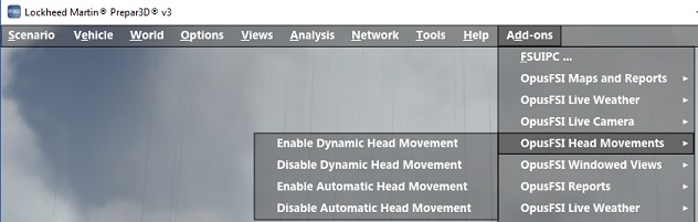
For this exercise click on the Enable
DHM checkbox, open the DHM dialog using the DHM
Options button and enable all
the DHM options, open the AHM dialog and enable all the AHM options then
close the AHM and DHM dialogs. N.B. AHM effects are automatically
disabled when using TrackIR.
Stage
Six - Assign a joystick button or key to the view
Click in the upper Joystick Button / Key
Sequence box to assign a joystick button, click in the lower box to
assign a key command. Any assigned key command must not be used
elsewhere (FSX, FSUIPC etc.), if it is then FSX will refuse to relay the
key press event to the OpusFSI interface. The OpusFSI interface will
accept buttons 1 through to 32 of Joysticks 1 through to 8. All button
and registered key events are displayed within the Spy window when the
button or key is pressed. If they are not displayed then the joystick or
button is invalid, not registered within FSX, already assigned
elsewhere, or just an illegal entry.
Finally don't forget to click on OK
before closing the Camera Editing dialog. Your default virtual cockpit
view should now be defined and saved within the FSXSERVER.CAM (or
P3DSERVER.CAM file for P3D).
You can repeat this exercise and move the eye point across to the right
hand seat position to create the non-default First Officer's position.
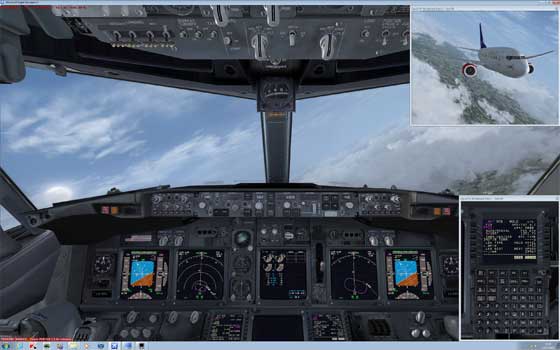
Windowed Views
Windowed views are
ideally suited to computer systems equipped with either multiple screens or
single large screens. DHM cannot be specified for windowed view types. Windowed
views cannot be associated with joystick buttons or keyboard keys, they are
automatically opened when the aircraft is loaded and then must be manually
undocked (if required) prior to using the Restore Win option to restore their
sizes and positions.
It
is not possible to alter the camera's eye point in windowed views so they must
be edited in the main window. The settings for the view are specified entirely
within the FSX or Prepar3D aircraft.cfg files.
Separate sizes and
positions are stored for your docked and
If you
make changes to an aircraft's windowed views, other than a zoom adjustment, you
must force FSX or Prepar3D to reload the modified aircraft.cfg file. This can
only be achieved by either restarting the simulator, or by first selecting a
different aircraft type then reloading your original aircraft.
Undocked windowed views must be
undocked manually before their size and positions can be saved or restored using
the Save Win and Restore Win button options, or the Save Windowed
Views and Restore Windowed Views options within the simulator's OpusFSI menu.
After you have moved
and resized all the windowed views use the server or client program's Save
Win button option to save the layout of your system. This option saves the
position and sizes of all your
docked and undocked windowed views on the server or client system, this gives
you the option of restoring the screen layout in the future with the Restore
Win button (or simulator's OpusFSI
menu).
Displaying
There are three steps
involved in displaying windowed views,
·
Open the windowed view
·
Undock if required
·
Restore the size and position
Opening the Windowed View
Windowed views cannot
be associated with joystick button or key commands. Windowed views are displayed
automatically each time you change the aircraft selection or load a flight.
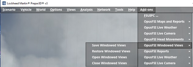
You can also control
the windowed view display using either the Open
Win (and Close Win) buttons on
the server and client program forms, or via the Open Windowed Views and Close
Windowed Views options within the simulator's OpusFSI add-on menu.
Undocking Windowed Views
Windowed views are
displayed in an identical manner to the simulator's 'Views - New View' menu
option, they appear as docked new view windows within the simulator's main
display. You can undock the windowed view if you wish but windowed views cannot
be undocked automatically within FSX or Prepar3D, therefore,
All windowed views must be undocked
manually by the user.
Manually
undock them by right-clicking in the window area and selecting the Undock
Window option.
Finally,
if you have previously saved the windowed views position and sizes using the Save
Win button then use the Restore Win
button to restore the previously saved position and sizes of each of your docked
and undocked windows. These button options are provided on the server and each
of the client programs. These options are also available via the simulator's OpusFSI
add-on menu.
The Save
Win and Restore Win options reduce the process of preparing for a flight to
the following three simple steps,
1.
Load the aircraft and flight into the simulator
2.
Either leave the windowed views docked, or undock
them as required.
3.
Either click on the server or client program's Restore
Win button, or select the Restore
Windowed Views menu option within the simulator.
This procedure has to
be repeated on each system displaying windowed views.
Warning - the Restore process will not work if you
have a TH2Go device, the device changes the window sizes and positions making
them unknown to other software.
Windowed Views
Tips
for Creating Windowed Views
The
software only works with views you create using Live Camera, in other words its
own camera views and not views you open using the sim menus.
1.
Windowed views can only be created by the software editing your aircraft.cfg
files in the simulator's SimObjects folders, located in
<FSX>\SimObjects\Airplanes and <FSX>\SimObjects\Rotorcraft. If you
look in these folders you will find an aircraft.cfg file. You can open these
files using Notepad, if you go to the bottom of the aircraft.cfg file you will
find our camera definition for the custom External Views.
[CameraDefinition.899]
Title
= "OpusFSI Aircraft View"
Guid
= {01021987-E220-6507-1024-462840738899}
Description
= OpusFSI Aircraft View
...
If
you have successfully created a Windowed view you will also see that view
appended here ...
For
example,
Title
= "OpusFSI Windowed View 1"
Guid
= {01021987-E220-6507-1024-462840738990}
Description
= OpusFSI Customized External View
...
If
CameraDefinition.899 is missing then you either have the Live Camera feature
disabled or the LC software cannot access your aircraft.cfg files. The
aircraft.cfg files are amended each time OpusFSI server program is run and when
you click on Save Cameras, which you must do to save your camera views.
The
Getting Started guide for Single PCs (and Networked PCs) has sections describing
how to set the sharing and permissions on drives and individual folders. If you
have the above CameraDefinition.899 missing then you most likely will have to
make sure the relevant drives and folders are shared. First alter the drive
containing FSX, then share the FSX installation folder itself. It is quite a
simple process.
2.
After OpusFSI has made changes to the cfg files you must load an entirely
different aircraft type and reload the original aircraft to force FSX to reload
the cfg data, including the modified CameraDefinitions contained within.
3.
Windowed views cannot be Undocked by the software, there is no facility in FSX
that allows this. So when Windowed views are displayed, if you want them
Undocked then you must do it manually by right-clicking in the window.
4.
Windowed views should not be assigned with any button or key commands. They are
displayed automatically when you select the aircraft and when you click on the
Open Views button.
5.
To assist you, when the view is displayed you should Undock the view, reposition
and resize it, then click on the Save Win
button. Next time the view is displayed and Undocked (by you), you can then
click on Restore Win and the software
will attempt to reposition and size the window for you.
Warning
- this process will not work if you have a TH2Go device, the device messes with
the window sizes and positions making them unknown to other software.
6.
Another useful test to check you have a correct view setup is to load your
flight then use the S key to cycle through your view types. You should see (in
the top right-hand corner) the following view types ...
Virtual
Cockpit ->
Outside View ->
Tower View ->
Aircraft View ->
Custom View OpusFSI External View
before
it then cycles back to the VC view.
Windowed Views and Frame Rates
Windowed
views are ideally suited for use on the 'non-flying' client systems. On these
systems, by their very nature, the use of multiple windowed views will have far
less of an impact on the displayed frame rates than say on the main 'flying'
server system.
In
fact, the use of multiple windowed views on the main 'flying' server may result
in considerable reduction in frame rates, especially if you are using a complex
aircraft such as the PMDG 737NGX, or you are operating close to an airport with
complex scenery (e.g. during the takeoff and landing phases of the flight).
However, there will be far less impact on the frame rates during the cruising or
decent phases of flight.
Windowed
views will always have a considerable effect on the frame rates within the
Lockheed Martin Prepar3D simulator, on both server and client systems.
The
Open Win and Close Win buttons on the server and client program
forms, and the Open Windowed Views and Close Windowed Views
options within the simulator's OpusFSI menu, can be used to remove and
re-display all windowed views whilst flying.
These
options give you control over the display of the configured windowed views, most
useful on the main 'flying' server system. For example, you can close all
windowed views during certain 'high-demand' phases of flight, and re-open them
during the less demanding phases.
For
your convenience, the restore, close, and open view options have been duplicated
as Restore Windowed Views, Close Windowed Views, and Open Windowed
Views options within the FSX and Prepar3D simulator's OpusFSI Menu.
Creating
Panoramic Views
2D
cockpit views are generally used on the client systems to create panoramic
(scenic) views. On the client systems this is achieved by setting the 2D panel
transparency to 100% (making the panel invisible) and then setting up the client
views via the server's Camera Control dialog. On the main 'flying' server system
it is up to the user to press Shift-1
to disable the 2D panel display. Note, the eye position will be different with
the 2D panel enabled so you should always disable the panel when displaying
scenic views on the server.
Please
refer to the OpusFSI_v5 Getting Started Networked
PCs guide for detailed instructions on setting up your client systems.
Any
2D cockpit view that is panned more than 45 degrees either side will reveal the
virtual cockpit walls. The cockpit walls can all be eliminated by simply moving
the 2D cockpit views forward a few meters. For example, setting the Z-axis to
2.0 will move the eye position forward by 2 meters and usually fix your eye
point outside the invisible 2D cockpit. You will need to experiment with your
selected aircraft cockpit by adjusting the Z-axis and panning the Yaw-axis
around to cover the full extent of your intended panoramic vista.
If
you are using windowed view to create a panoramic vista, you can use the Display Windowed View button to display one or more windowed views
to assist you in creating and aligning the current view. You may also find it
helpful to undock the simulator's main view during this process, this will allow
you to adjust the shape, position, and size of the main window aligning it with
the other displayed windowed views. You may also find it helpful to use the Stepped camera control to make fine adjustments to the camera's eye position.
If
you create a panoramic vista without using windowed views (i.e. on systems not
using multi-screened PCs) then not only will you achieve the optimum system
performance but you will be able to change the displayed vista with a single
button or key press. To achieve this simply assign the same button or key press
to the required set of views on your server and client systems. Each set of
views would be configured with a different eye position or perspective. For
example, you could recreate the same panoramic vista using external aircraft
views with the eye point moved 50 meters behind the aircraft.
Out
of Sync - OpusFSI External Views
The number of available view modes can be determined
simply by pressing the 'S' key and counting the total number of view
modes that can be cycled. The normal sequence in the simulator is,
VC
- Spot - Tower - Aircraft - External
Giving a total of five (5) different view modes.
Opus sets each of these view types as CycleHidden=No.
You should ensure you have not hidden any of these
views by setting their CycleHidden field to Yes in the aircraft.cfg or
cameras.cfg files. Also ensure the cfg files are not write protected.
If you display an external
view within the main viewing area and get the wrong external view then
use the A or Shift-A keys to cycle back to the OpusFSI External View,
after that everything will be back in sync.
World Views
Introduction
World Views are cameras that have been fixed at a specified latitude, longitude, and altitude. All World Views are defined within the simulator's Cameras.CFG file (in your AppData Roaming folder) and their Camera Definitions are read in by the simulator only on start up.
Live Camera automatically modifies your simulator's Cameras.CFG AppData file based on your current World View camera configuration. After creating, cloning, or editing (making changes) to any of your World Views you must shutdown and restart both your simulator (FSX, FSX Steam Ed, or P3D) and the OpusFSI FSI SERVER program.
Limitations
You can create up to 99 World Views on your system but will generally only need a few defined at your favourite airports, or multiple views defined at the same airport specifically for video making or plane spotting.
Be warned there are limitations
and plenty of unfinished features or bugs within the sim code relating
to fixed type cameras. These problems cannot be overcome in software due
to the incomplete support for camera control within SimConnect and
general lack of monitoring and view control within the FSX simulator
code (the same limitations and problems are found in the FSX Steam
Edition and Prepar3D simulators).
WARNINGS
...
1.
Camera Positioning Error
The
Lat/Lon coordinates for all World Views (Fixed Cameras) within the sim
are stored with very limited accuracy hence the camera position may end
up shifted N/S or E/W depending on the coordinates. You will have to use
trial and error, shifting the view to compensate for this limited
accuracy within the sim.
2.
Change of Hemisphere Bug
The sim does not like displaying World
Views (Fixed Cameras) located in different N/S or E/W hemispheres. This
is a bug that results in corrupting the stored data for all the World
Views in the sim. The sim will continue functioning, however all World
Views will be corrupted until the sim is restarted. Solution - don't
display World Views in different hemispheres.
These problems however can be
overcome by adhering to the following simple rules,
DOs ...
1. DO assign a 'unique' button or
key sequence to your World Views (see below).
2. DO use the assigned World View
button or key sequence to display a World View.
When an assigned button or key
sequence is detected the software selects or cycles to the
configured World View that,
a)
has been assigned to that button or key sequence, and
b)
is currently within 48km (30 miles) of your present position.
Under normal circumstances we
therefore recommend you assign the same button or key sequence to ALL
your World Views. Use of this 'unique' assigned button or key sequence
will always display or cycle to the World View(s) local
to your current position.
If you have multiple World Views
configured at the same location then you can either assign separate or
common button/key sequences to each view at that location, or you can
manually select the view you want via the simulator's Views->View
Mode->Custom Menu. Warning - NEVER manually select a distant World
View (see the DON'T section below).
If you do not assign buttons or
key sequences to World Views you can still select them manually via the
simulator's Views->View Mode->Custom Menu provided you are very
careful and never manually select a distant World View.
DON'Ts ...
1. NEVER use the menu to select a
World View that is not near to your present position.
2. NEVER use the 'A' key to cycle
when any OpusFSI External or World View is displayed.
3. NEVER relocate the aircraft or 'Go to airport' when
a World View is on display.
4. NEVER display World Views defined in opposite
hemispheres.
The only time you should use the
'A' key to cycle through World Views is when you know for certain that
ALL the selected World Views will be nearby to your current position.
Nearby in this case is assumed to be within 48km or 30 miles.
If you do select a distant World
View that is say on the other side of the globe or in a different
hemisphere then it will most likely result in the faulty FSX code
corrupting ALL World View configuration data held within its memory. The
sim will most likely continue to function as normal but NONE of the
configured World Views will work as expected. The effects in the sim may
be unpredictable and the only recovery will be to restart the simulator
!
If you NEVER display a distant
World View the sim will be happy.
Creating
World Views
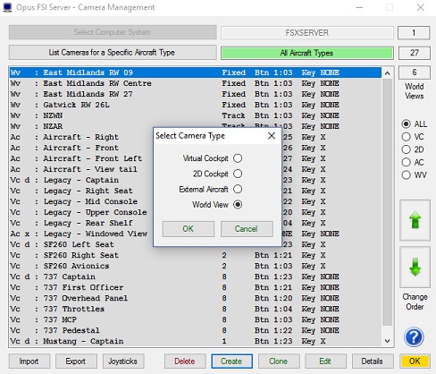
Click on the Create option within the Camera Management dialog then select the World
View camera type and click OK.
The simulator's display will be initialised at your aircraft's current
latitude, longitude, and altitude.
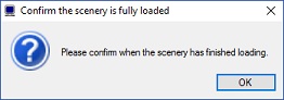
Wait until the scenery has finished loading then click OK on the prompt.
Cloning
World Views
Highlight the World View camera
you wish to clone within the Camera Management list then click on the Clone option. The simulator will automatically slew to the World
View's configured latitude, longitude and altitude. The Confirm the
scenery is fully loaded dialog will then be displayed. Click on the OK button ONLY after the scenery has finished loading and displaying
on the simulator, normally indicated by all the runway markings
appearing along with all airport infrastructure.
Editing
World Views
Highlight the World View you wish
to edit within the Camera Management list then click on the Edit option. The simulator will automatically slew to the World
View's configured latitude, longitude and altitude. The Confirm the
scenery is fully loaded dialog will then be displayed. Click on the OK button ONLY after the scenery has finished loading and displaying
on the simulator, normally indicated by all the runway markings
appearing along with all airport infrastructure.
General
Editing ...
All camera editing should be
carried out with the simulator operating in Windowed Mode (as opposed to
Full Screen Mode where you will not be able to access the OpusFSI
dialogs).
All World View camera editing
should be carried out with your aircraft stationary on the ground.
World Views can be Created,
Cloned, and Edited via the Camera Management dialog. When the World View
Edit dialog is displayed the simulator will automatically be placed in
2D Cockpit and Slew mode.
If the 2D panel is on display you
can remove it by right clicking on the panel and using the Close Window
option. The 2D panel can also be toggled on and off the display using
the simulator's Views->Instrument Panel->Main Panel menu option.
In edit mode you can use the
simulator's normal Slew Commands to slew your aircraft to the desired
World View (fixed) camera position. You can also use the World->Go
to Airport menu option to relocate your aircraft to a different part
of the globe. In doing this you may need to use the World->Time and Season menu option to restore daylight
conditions.
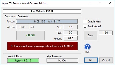
World View Name
Specify the name of the World View
in this edit box (e.g. East Midlands RW 09). This is the name (preceded
with OpusFSI) that will appear on the screen and within the simulator's
Views->View Mode->Custom menu.
Assign Button
After making any adjustments
slewing your aircraft, the Assign button option MUST be used to record
the aircraft's current position, altitude and attitude. The World View's
'assigned' position and altitude are displayed within the dialog. The
aircraft's attitude (pitch, bank, and heading) are recorded but not
displayed. The assigned pitch, bank and heading are generally only
relevant in Non-Track mode.
Disable View
Tick this box if you want to
disable or remove the World View from the simulator's Cameras.CFG
configuration. When ticked the World View will not be selectable nor
will it appear within the simulator's Views->View
Mode->Custom menu.
Track Aircraft
Tick this box if you want the
World View to always track and point toward your aircraft's current
position.
Zoom
The default zoom level for all World Views is 1.00. You can use this option to alter the zoom to any desired setting.
Joystick Button and Key Sequence
When an assigned button or key sequence is detected the
software selects or cycles to the assigned World View that
is within 48km (30 miles) of your present position.
Displaying World Views
When you display a World View using an assigned button or key sequence you will notice the OpusFSI External View momentarily flash onto the screen. This is deliberate and necessary as Live Camera must first select the OpusFSI External View, prepare the sim's display and allow the sim time to settle before cycling or stepping to the chosen World View.
Spy Messages
We have left some of the Spy messages in the software. These
messages can be seen by clicking on the top right-hand Spy button on the server's main form. These messages will indicate
when the mode changes occur within the software; the mode will change between
TAXIING, AIRBORNE, and LANDING and are indicated with the following messages.
SIM TAXIING
SIM AIRBORNE
SIM LANDING
, Accel
xxxx ,
Factor x.xxx
Where on landing, the vertical acceleration (in units of 100 x feet
per second squared) is displayed as 'Accel xxxx',
and the resulting severity factor (< 1.0 for smoother landings, 1.0 for
normal landings, and > 1.0 for heavier landings) is displayed as 'Factor
x.xxx'. At present, normal landings have an assumed acceleration of 8
feet per second squared. The Spy window automatically closes after two minutes.
Home About Us Products Downloads FAQ Gallery Testimonials Contact Links